Parloma Robotic Hand Builds and Upgrades
Parloma Robotic Hand Builds and Upgrades
In order to gather real-word data through human interaction trials, two robotic hand and forearm prototypes had been assembled. During the process, few parts of the overall system showed up to require some redesign due to poor functionality and/or lack of robustness. Those upgrades are mostly about control communication, power supply distribution and the external control box.
The Hand
The hands, like much of the forearms, had been reproduced from the original Parloma model: 24 3D-printed PLA parts put together with glue, self-tapping M2 screws, 8mm alluminum/2mm steel joint axes and 45x3x0.3mm springs.
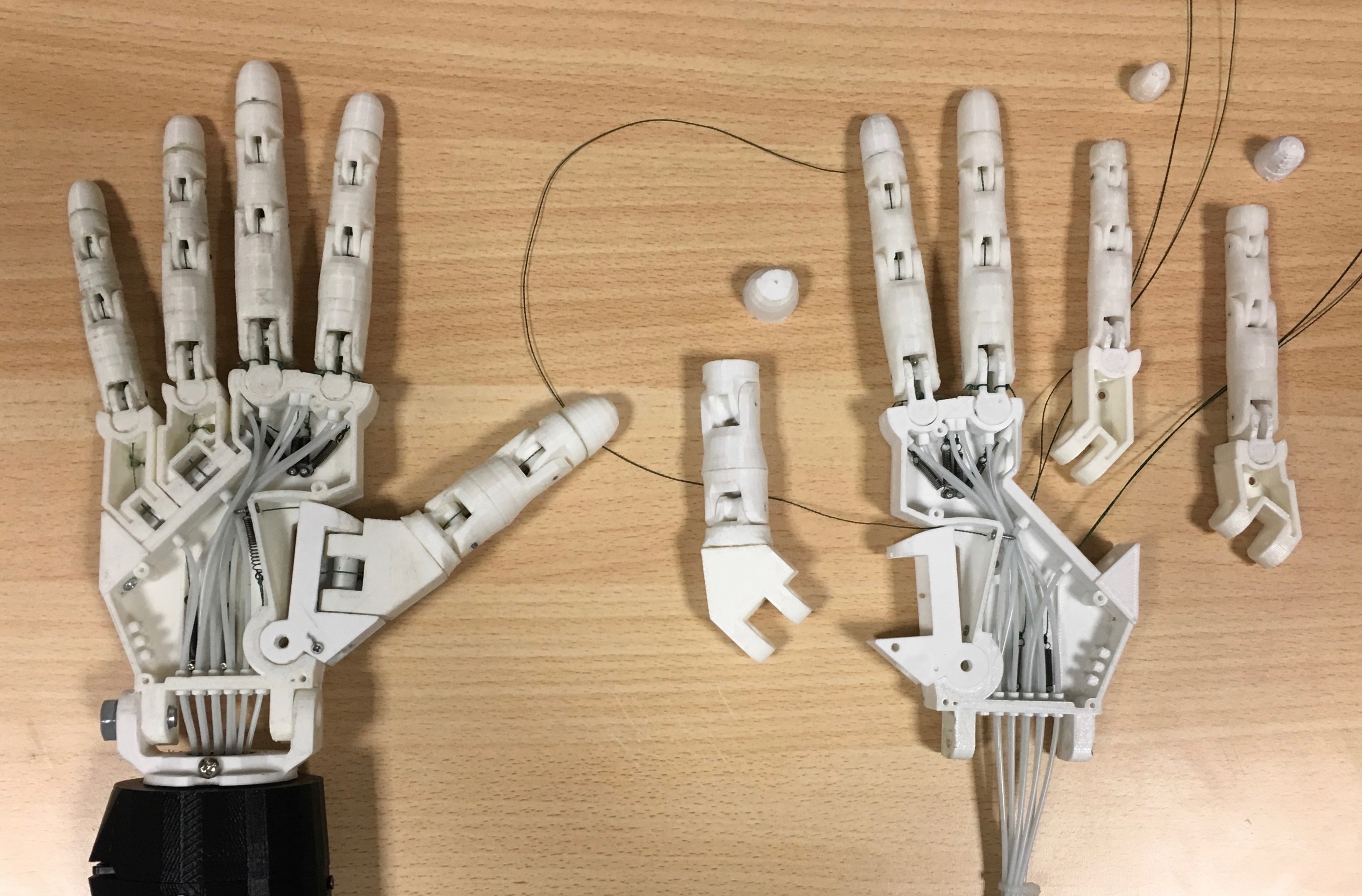
Post-processing the printed parts has been critical in order to add tolerances making them fit together or slide in case of joints.
Bowden pipes made out of Teflon (PTFE) had been used to route the artificial tendons through smooth paths within the palm end the forearm toward the motor’s pulleys.
The Forearm
The forearm is where the actuation unit is located, servo motors and power electronics, fastened on support structures inside the shell, generate forces that are trasmitted to the fingers trough bowden cables.
The outer structure of the forearm, the single-axis robotic wrist as well as the motors/bowden support frame, are kept identical to the original Parloma Project 3D models.
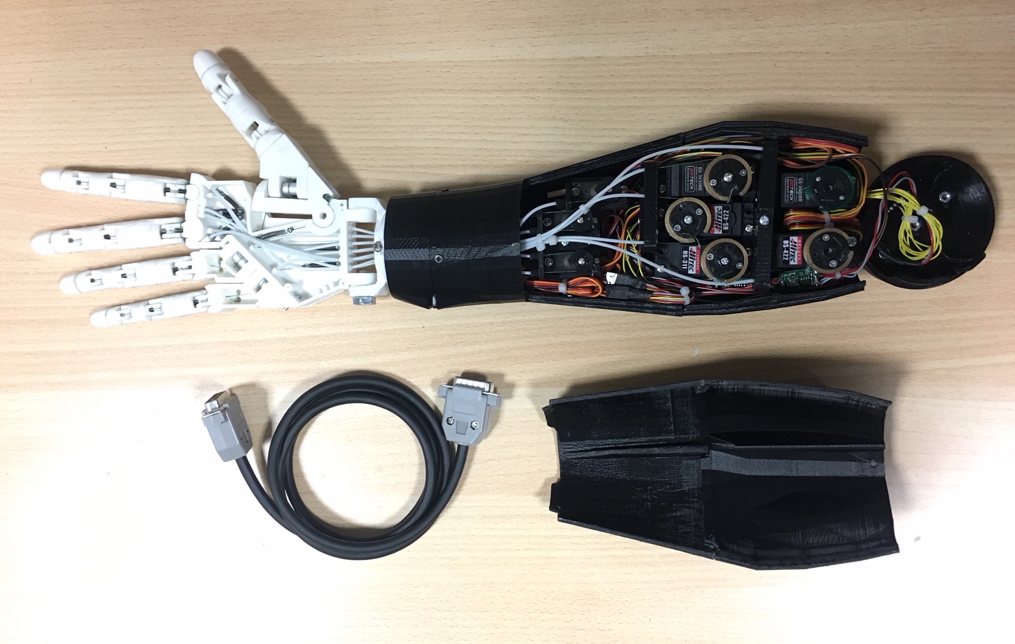
At this point, we’ve just started to introduce some necessary improvements. Like the main servo motors that have been upgraded to newer and digital options. Digital servos like the MG996R are capable of higher torque with more mechanical and thermal stability than their analog counterparts.
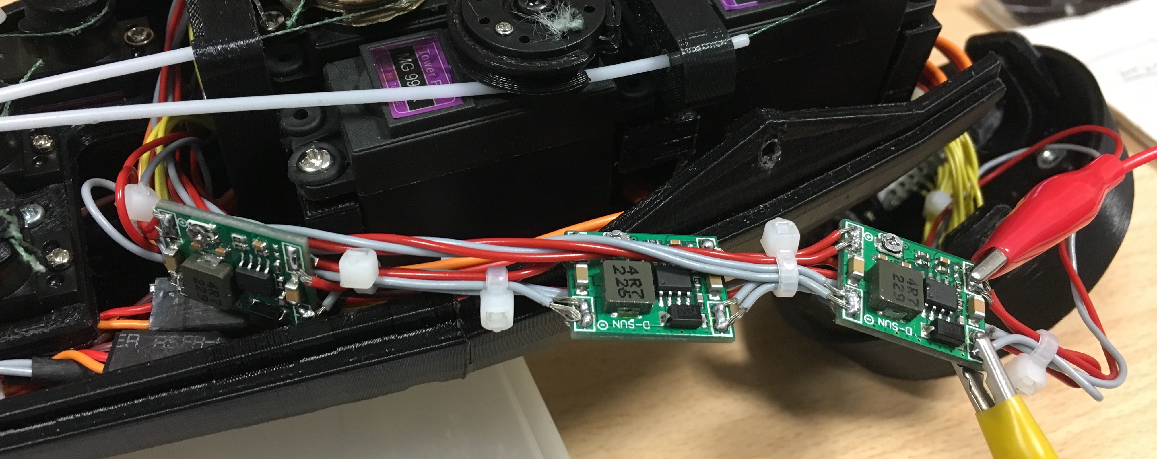
Servos power supply distribution and conditioning circuit have been improved as well, leveraging few miniaturized DC-DC step-down power converters, one for each couple of motors, integrated within the forearm and connected in parallel to the robot’s single 12V power input.
The base of the forearm has been redesigned introducing functionalities and improving robustness. It has been modeled in CAD combining parametrical and non-parametrical features to fit the organic shape of the forearm’s outer mesh geometry.
The main purpose of the component is to hold all the electrical connections of the robot, power supply and control data that are provided by the external control box through separate cables.
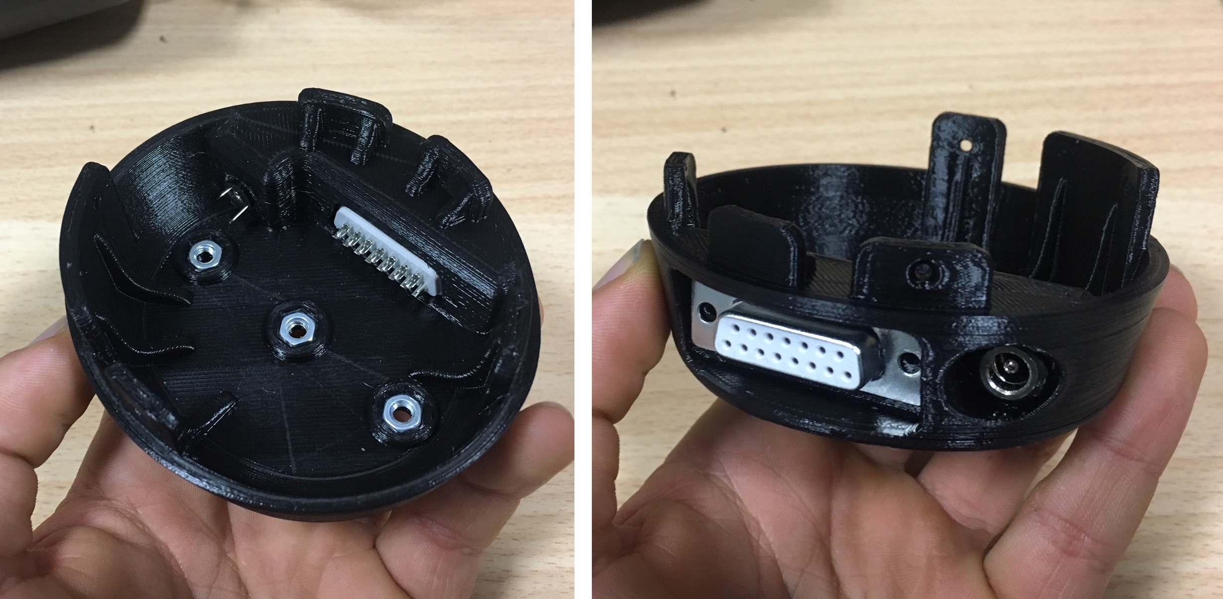
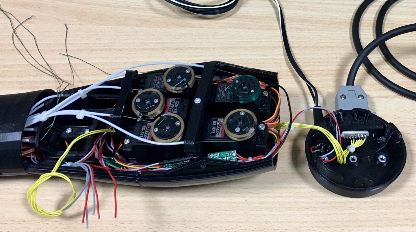
The connectors, upgraded to more robust options, has been moved to the side of the forearm and are now accessible in more installation scenarios while the extra volume in the component can store more electronics for future upgrades. The connection is also mechanical by means of 3 M4 nuts placed at the bottom surface.
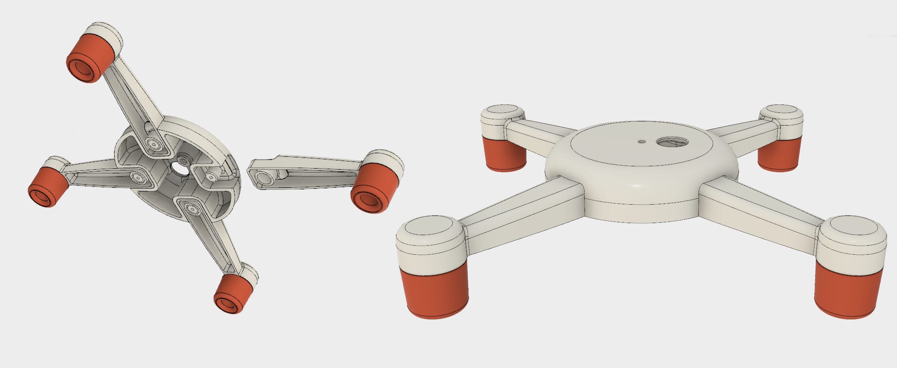
Just in case a more robust and stable holding system is needed, a simple modular support stand has beed designed for the purpose. It is compatible with the M4 screws lock system of the current forearm base as well as the older version.
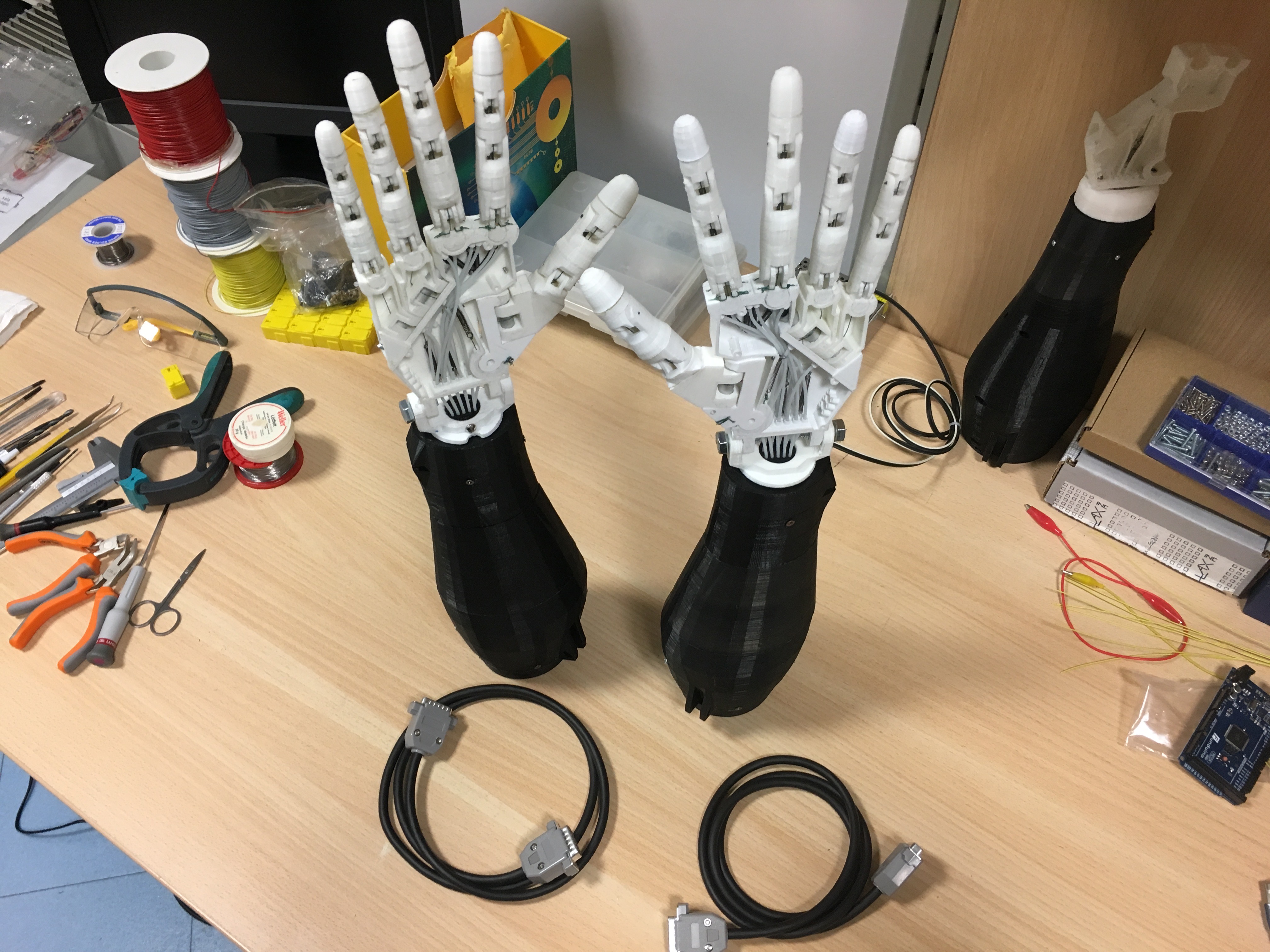
Both right and left robotic hands, once fully assembled and tested, look like this.
The Control Box
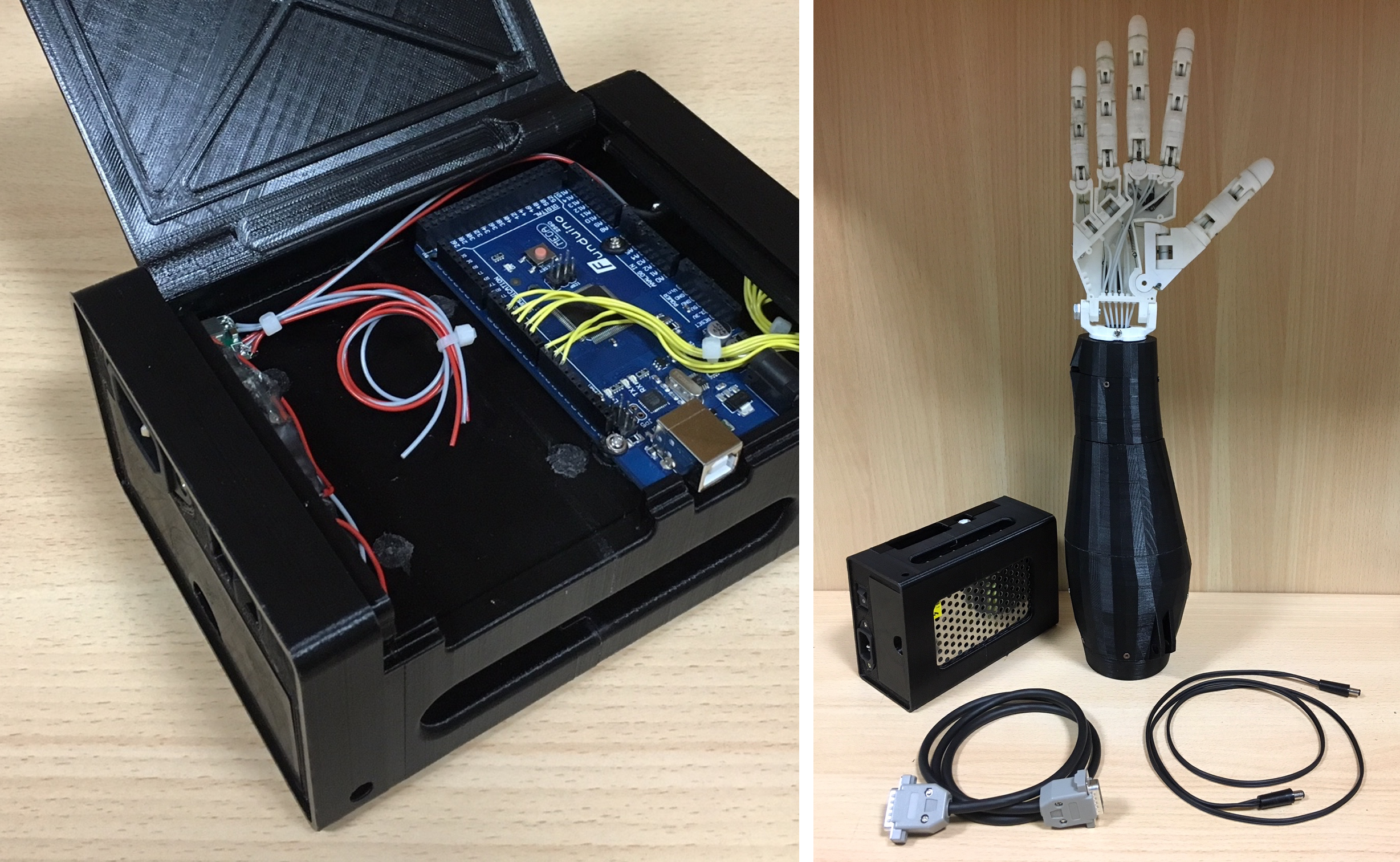
The control box is designed to store a Raspberry Pi 3, an Arduino Mega and the main power unit in single external module, providing all the necessary ports for a smooth set up of the system. It features also a hinged opening to allow easy access to the electronic boards.
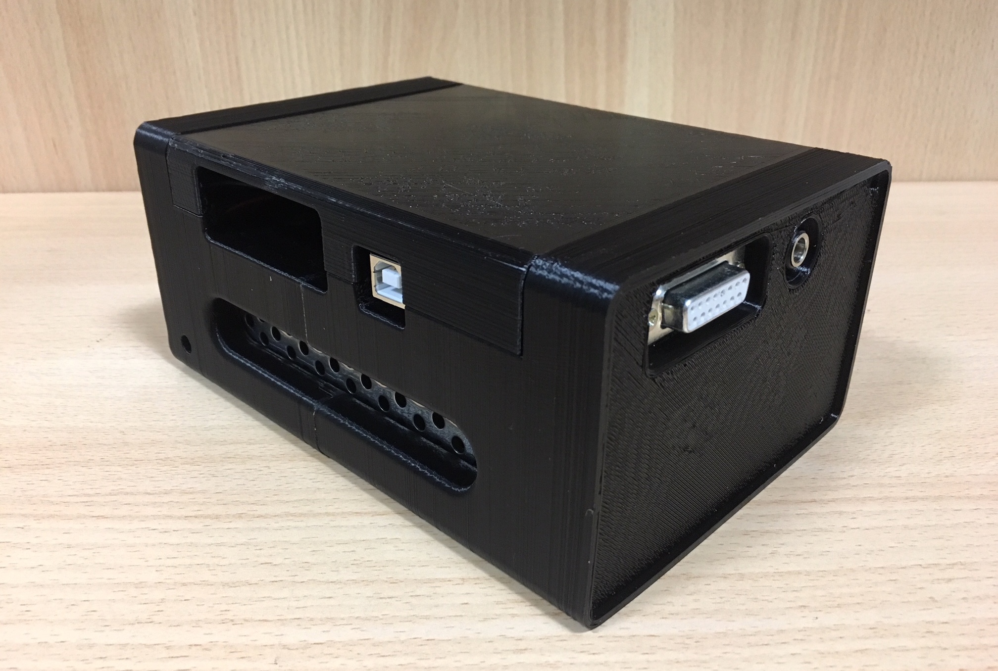
The module’s main structure is composed by two main printed parts glued together while the hinged top cover and the power unit side cover are printed sparately. The top cover hinge mechanism works on two M3x18 machine screws with a snap-fit locking system.
